PWM controller for motor with feedback. Collector motor speed controller: do-it-yourself device and manufacture
To adjust the speed of low-power collector-type electric motors, a resistor is usually used, which is connected in series with the engine. But this method of switching on provides a very low efficiency, and most importantly, it does not allow smooth speed control (finding a variable resistor of sufficient power for several tens of ohms is not at all easy). And the main drawback of this method is that sometimes the rotor stops when the supply voltage decreases.
PWM controllers, which will be discussed in this article, allow for smooth adjustment of speed without the disadvantages listed above. In addition, PWM controllers can also be used to adjust the brightness of incandescent lamps.
Figure 1 shows a diagram of one of these PWM controllers. The field-effect transistor VT1 is a sawtooth voltage generator (with a repetition rate of 150 Hz), and the operational amplifier on the DA1 chip works as a comparator that generates a PWM signal based on transistor VT2. The rotational speed is regulated by a variable resistor R5, which changes the pulse width. Due to the fact that their amplitude is equal to the supply voltage, the electric motor will not “brake”, and in addition, it is possible to achieve a slower rotation than in normal mode.
![]()
The PWM controller circuit in Fig. 2 is similar to the previous one, but the master oscillator here is made on an operational amplifier (op-amp) DA1. This op amp functions as a triangular voltage pulse generator with a repetition rate of 500 Hz. Variable resistor R7 allows smooth adjustment of rotation.
![]()
In Fig.3. a very interesting controller scheme is presented. This PWM regulator made on the integral timer NE555. The master oscillator has a repetition rate of 500 Hz. The duration of the pulses, and, consequently, the frequency of rotation of the rotor of the electric motor can be adjusted in the range from 2 to 98% of the repetition period. Generator output PWM controller on the NE555 timer connected to a current amplifier made on a transistor VT1 and actually controls the motor M1.
The main disadvantage of the schemes discussed above is the absence of elements for stabilizing the shaft speed when the load changes. But the following scheme, shown in Fig. 4., will help solve this problem.
![]()
This PWM controller, like most similar devices, has a triangular-shaped voltage pulse generator (repetition frequency 2 kHz), made on DA1.1.DA1.2, a comparator on DA1.3, an electronic switch on a VT1 transistor, and a pulse duty cycle regulator , but in fact the frequency of rotation of the electric motor - R6. A feature of the circuit is the presence of positive feedback through resistors R12, R11, diode VD1, capacitor C2, and DA1.4, which ensures a constant speed of the motor shaft when the load changes. When connecting PWM controller to a specific electric motor with the help of resistor R12, the depth of the POS is adjusted, at which there are no self-oscillations in the speed of rotation with an increase or decrease in the load on the motor shaft.
Element base. In the circuits given in the article, the following analogues of parts can be used: the KT117A transistor can be replaced with KT117B-G or, alternatively, with 2N2646; KT817B - KT815, KT805; chip K140UD7 on K140UD6, or KR544UD1, TL071, TL081; timer NE555 on S555, or KR1006VI1; chip TL074 to TL064, or TL084, LM324. If it is necessary to connect a more powerful load to the PWM controller, the key transistor KT817 must be replaced with a more powerful field-effect transistor, as an option, IRF3905 or similar. The specified transistor is capable of passing currents up to 50A.
Another review on the topic of all sorts of things for homemade products. This time I will talk about digital controller revolutions. The thing is interesting in its own way, but I wanted more.
For those interested, read on :)
Having in the household some low-voltage devices such as a small grinder, etc. I wanted to slightly increase their functional and aesthetic appearance. True, this did not work out, although I still hope to achieve my goal, perhaps another time, I’ll tell you about the thing itself today.
The manufacturer of this regulator is Maitech, or rather, this name is often found on all kinds of handkerchiefs and blocks for homemade products, although for some reason I did not come across the site of this company.
Due to the fact that I did not end up doing what I wanted, the review will be shorter than usual, but I will start, as always, with how it is sold and sent.
The envelope contained an ordinary ziplock bag. 
The kit includes only a regulator with a variable resistor and a button, there is no hard packaging and instructions, but everything arrived intact and without damage. 
There is a sticker on the back that replaces the instructions. In principle, more is not required for such a device.
The operating voltage range is 6-30 Volts and the maximum current is 8 Amps. 
Appearance very good, dark "glass", dark gray plastic of the case, in the off state it seems generally black. In appearance offset, nothing to complain about. A transport film was glued on the front.
Installation dimensions of the device:
Length 72mm (minimum case opening 75mm), width 40mm, depth excluding front panel 23mm (with front panel 24mm).
Front panel dimensions:
Length 42.5, width 80mm 
A variable resistor comes with a handle, the handle is of course rough, but it will do for use.
The resistance of the resistor is 100KΩ, the adjustment dependence is linear.
As it turned out later, 100KΩ resistance gives a glitch. When powered from a pulsed power supply unit, it is impossible to set stable readings, the interference on the wires to the variable resistor affects, because of which the readings jump +\- 2 characters, but it would be fine to jump, along with this, the engine speed jumps.
The resistance of the resistor is high, the current is small and the wires collect all the noise around.
When powered by a linear PSU, this problem is completely absent.
The length of the wires to the resistor and the button is about 180mm. 
Button, well, there's nothing special. Normally open contacts, mounting diameter 16mm, length 24mm, no illumination.
The button turns off the engine.
Those. when power is applied, the indicator turns on, the engine starts, pressing the button turns it off, the second press turns it on again.
When the engine is off, the indicator also does not light up. 
Under the cover is the device board.
The power supply and motor connection contacts are brought out to the terminals.
The positive contacts of the connector are connected together, the power switch switches the negative wire of the engine.
The connection of the variable resistor and the button is detachable.
Everything looks neat. The capacitor leads are a bit crooked, but I think that this can be forgiven :) 
I will hide further disassembly under the spoiler.
More
The indicator is quite large, the height of the digit is 14mm.
The dimensions of the board are 69x37mm. 
The board is assembled neatly, there are traces of flux near the indicator contacts, but in general the board is clean.
The board contains: a reverse polarity protection diode, a 5 Volt stabilizer, a microcontroller, a 470 microfarad 35 Volt capacitor, power elements under a small radiator.
Places for installing additional connectors are also visible, their purpose is not clear. 
I sketched a small block diagram, just for a rough understanding of what and how it is switched and how it is connected. The variable resistor is turned on with one foot to 5 volts, the second to the ground. Therefore, it can be safely replaced with a lower denomination. There are no connections to the unsoldered connector in the diagram. 
The device uses a microcontroller manufactured by STMicroelectronics.
As far as I know, this microcontroller is used in a fairly large number of different devices, such as ammeters. 
Power stabilizer, when operating at the maximum input voltage, heats up, but not very much. 
Part of the heat from the power elements is removed to the copper polygons of the board, on the left you can see a large number of transitions from one side of the board to the other, which helps to remove heat.
Also, heat is removed with the help of a small radiator, which is pressed against the power elements from above. This placement of the heatsink seems a little doubtful to me, since the heat is removed through the plastic of the case and such a heatsink does not help much.
There is no paste between the power elements and the radiator, I recommend removing the radiator and smearing it with paste, at least a little but it will get better. 
A transistor is used in the power section, the channel resistance is 3.3mOhm, the maximum current is 161 Amperes, but the maximum voltage is only 30 Volts, so I would recommend limiting the input at 25-27 Volts. When operating at near-maximum currents, there is a slight heating.
A diode is also located nearby, which dampens the current surges from the self-induction of the motor.
10 amps, 45 volts are applied here. There are no questions about the diode. 
First inclusion. It so happened that I carried out the tests even before removing the protective film, because in these photos it is still there.
The indicator is contrasting, moderately bright, reads perfectly. 
At first I decided to try on small loads and got the first disappointment.
No, I have no complaints about the manufacturer and the store, I just hoped that such a relatively expensive device would have engine speed stabilization.
Alas, this is just an adjustable PWM, the indicator displays% filling from 0 to 100%.
The regulator didn’t even notice the small motor, the day it is a completely ridiculous load current :) 
Attentive readers must have paid attention to the cross-section of the wires with which I connected the power to the regulator.
Yes, then I decided to approach the issue more globally and connected a more powerful engine.
Of course, it is noticeably more powerful than the regulator, but at idle its current is about 5 amperes, which made it possible to check the regulator at modes closer to the maximum.
The regulator behaved perfectly, by the way, I forgot to indicate that when turned on, the regulator smoothly increases the PWM filling from zero to the set value, ensuring smooth acceleration, while the indicator immediately shows the set value, and not like on frequency drives, where the real current is displayed.
The regulator did not fail, warmed up a little, but not critical. 
Since the regulator is pulsed, I decided, just for fun, to poke around with an oscilloscope and see what happens at the gate of the power transistor in different modes.
The PWM frequency is about 15 kHz and does not change during operation. The engine starts at approximately 10% fill. 

Initially, I planned to put the regulator in my old (rather already ancient) power supply for small power tools (more on that some other time). in theory, it should have become instead of the front panel, and the speed controller should have been located on the back, I didn’t plan to put a button (fortunately, when turned on, the device immediately switches to the on mode).
It had to be nice and neat. 
But further disappointment awaited me.
1. Although the indicator was a little smaller in size than the front panel insert, it was worse that it did not fit in depth, resting against the racks for connecting the halves of the case.
and if the plastic of the indicator housing could be cut off, then it would not matter, since the regulator board interfered further.
2. But even if I would have solved the first question, there was a second problem, I completely forgot how my power supply was made. The fact is that the regulator breaks the minus supply, and I have a relay for reverse, turning on and forcing the engine to stop, and a control circuit for all this. And with their alteration, everything turned out to be much more difficult :(
If the regulator was with speed stabilization, then I would still get confused and redo the control and reverse circuit, or redo the regulator for switching + power. And so it is possible and I will redo it, but already without enthusiasm and now I don’t know when.
Maybe someone is interested, a photo of the insides of my PSU, it was going to be about 13-15 years ago, almost all the time it worked without problems, once I had to replace the relay. 
Summary.
pros
The device is fully functional.
Neat appearance.
Quality build
The kit includes everything you need.
Minuses.
Incorrect operation from switching power supplies.
Power transistor without voltage margin
With such a modest functionality, the price is too high (but everything is relative here).
My opinion. If you close your eyes to the price of the device, then in itself it is quite good, and it looks neat and works fine. Yes, there is a problem of not very good noise immunity, I think that it is not difficult to solve it, but it is a little frustrating. In addition, I recommend not to exceed the input voltage above 25-27 Volts.
More frustrating is the fact that I looked quite a lot of options for all kinds of ready-made regulators, but nowhere do they offer a solution with speed stabilization. Perhaps someone will ask why I do this. I will explain how a grinding machine with stabilization fell into the hands, it is much more pleasant to work than usual.
That's all, I hope it was interesting :)
The product was provided for writing a review by the store. The review is published in accordance with clause 18 of the Site Rules.
I plan to buy +23 Add to favourites Liked the review +38 +64The DC motor speed controller circuit operates on the principles of pulse width modulation and is used to change the speed of a DC motor by 12 volts. Regulation of the motor shaft speed using pulse-width modulation gives greater efficiency than using a simple change in the DC voltage supplied to the motor, although we will also consider these schemes
DC motor speed controller 12 volt circuit

The motor is connected in a circuit to a field-effect transistor, which is controlled by pulse-width modulation carried out on the NE555 timer chip, which is why the circuit turned out to be so simple.

The PWM controller is implemented using a conventional pulse generator on an astable multivibrator, generating pulses with a repetition rate of 50 Hz and built on the popular NE555 timer. The signals coming from the multivibrator create a bias field on the gate field effect transistor. The duration of the positive pulse is adjusted using the variable resistance R2. The higher the duration of the positive pulse arriving at the gate of the field-effect transistor, the more power is supplied to the DC motor. And per turn, the shorter the pulse duration, the weaker the motor rotates. This circuit works great on a 12 volt battery.
DC motor speed control circuit for 6 volts
The speed of the 6 volt motor can be adjusted from 5-95%
Engine speed controller on the PIC controller
The speed control in this circuit is achieved by applying voltage pulses of various durations to the electric motor. For these purposes, PWM (pulse width modulators) are used. In this case, pulse-width regulation is provided by the PIC microcontroller. To control the engine speed, two buttons SB1 and SB2, "More" and "Less", are used. You can change the rotation speed only when the "Start" toggle switch is pressed. In this case, the pulse duration changes, as a percentage of the period, from 30 - 100%.
As a voltage stabilizer of the PIC16F628A microcontroller, a three-pin stabilizer KR1158EN5V is used, which has a low input-output voltage drop of only about 0.6V. The maximum input voltage is 30V. All this allows the use of motors with voltages from 6V to 27V. In the role of a power key, a composite transistor KT829A is used, which is desirable to be installed on a radiator.
The device is assembled on a printed circuit board measuring 61 x 52mm. You can download the PCB drawing and the firmware file from the link above. (See archive folder 027-el)

PWM DC motor speed controller
This homemade scheme Can be used as a speed controller for a 12V DC motor up to 5A rating or as a dimmer for 12V halogen and LED lamps up to 50W. The control is carried out using pulse-width modulation (PWM) at a pulse repetition rate of about 200 Hz. Naturally, the frequency can be changed, if necessary, by selecting for maximum stability and efficiency.
Most of these structures are assembled according to a much simpler scheme. Here we present a more advanced version that uses a 7555 timer, a bipolar transistor driver and a powerful MOSFET. This circuitry provides improved speed control and operates over a wide load range. This is indeed a very effective circuit and the cost of its parts when buying for self-assembly is quite low.
PWM controller circuit for a 12 V motor
![]()
The circuit uses a 7555 Timer to create variable pulse widths around 200 Hz. It controls transistor Q3 (through transistors Q1 - Q2) which controls the speed of an electric motor or lights.
![]()
![]()
There are many uses for this circuit that will be powered by 12V: electric motors, fans, or lamps. It can be used in cars, boats and electric vehicles, model railways and so on.
![]()
12 V LED lamps, such as LED strips, can also be safely connected here. Everyone knows that LED lamps are much more efficient than halogen or incandescent lamps, they will last much longer. And if necessary, power the PWM controller from 24 or more volts, since the microcircuit itself with a buffer stage has a power stabilizer.
 AC motor speed controller
![]() PWM controller for 12 volts
PWM controller for 12 volts
 Half-bridge DC Regulator Driver
 Scheme of the minidrill speed controller
Diagrams and overview of 220V electric motor speed controllers
To smoothly increase and decrease the speed of rotation of the shaft, there is a special device - a 220v electric motor speed controller. Stable operation, no voltage interruptions, long service life are the advantages of using a 220, 12 and 24 volt engine speed controller.
- Why do you need a frequency converter
- Application area
- Choose a device
- FC device
- Device types
- triac device
- Proportional signal process
Why do you need a frequency converter
 The function of the regulator is to invert the voltage of 12.24 volts, ensuring smooth start and stop using pulse-width modulation.
Speed controllers are part of the structure of many devices, as they provide electrical control accuracy. This allows you to adjust the speed to the desired value.
Application area
The DC motor speed controller is used in many industrial and domestic applications. For example:
- heating complex;
- equipment drives;
- welding machine;
- electric ovens;
- vacuum cleaners;
- Sewing machines;
- washing machines.
Choose a device
![]() In order to select an effective regulator, it is necessary to take into account the characteristics of the device, the features of the purpose.
In order to select an effective regulator, it is necessary to take into account the characteristics of the device, the features of the purpose.
- For collector motors, vector controllers are common, but scalar ones are more reliable.
- An important selection criterion is power. It must correspond to the permissible on the used unit. And it is better to exceed for the safe operation of the system.
- The voltage must be within acceptable wide ranges.
- The main purpose of the regulator is to convert the frequency, so this aspect must be selected according to the technical requirements.
- You also need to pay attention to the service life, dimensions, number of inputs.
FC device
- AC motor natural controller;
- drive unit;
- additional items.
The 12 V engine speed controller circuit is shown in the figure. The speed is controlled by a potentiometer. If the input receives pulses with a frequency of 8 kHz, then the supply voltage will be 12 volts.
The device can be purchased at specialized points of sale, or you can make it yourself.

AC speed controller circuit
When starting a three-phase motor at full power, current is transferred, the action is repeated about 7 times. The strength of the current bends the motor windings, heat is generated for a long time. The converter is an inverter that provides energy conversion. The voltage enters the regulator, where 220 volts are rectified using a diode located at the input. Then the current is filtered by means of 2 capacitors. PWM is formed. Further, the pulse signal is transmitted from the motor windings to a certain sinusoid.
There is a universal 12v device for brushless motors.
To save on electricity bills, our readers recommend the Electricity Saving Box. Monthly payments will be 30-50% less than they were before using the saver. It removes the reactive component from the network, as a result of which the load and, as a result, the current consumption are reduced. Electrical appliances consume less electricity, reducing the cost of its payment.

The circuit consists of two parts - logical and power. The microcontroller is located on the chip. This scheme is typical for a powerful engine. The uniqueness of the regulator lies in its use with various types engines. The power supply of the circuits is separate, the key drivers require 12V power supply.
Device types
triac device
The simister (triac) device is used to control lighting, the power of heating elements, and the speed of rotation.
 The triac controller circuit contains a minimum of the details shown in the figure, where C1 is a capacitor, R1 is the first resistor, R2 is the second resistor.
With the help of the converter, the power is regulated by changing the time of the open triac. If it is closed, the capacitor is charged by the load and resistors. One resistor controls the amount of current, and the second regulates the rate of charge.
When the capacitor reaches the voltage limit of 12V or 24V, the key is activated. The simister goes into the open state. When the mains voltage passes through zero, the simister is locked, then the capacitor gives a negative charge.
Converters on electronic keys
Common thyristor regulator with a simple operation scheme.

Thyristor, works in an alternating current network.
A separate type is the AC voltage stabilizer. The stabilizer contains a transformer with multiple windings.

DC stabilizer circuit

Charger 24 volt on thyristor
To a voltage source of 24 volts. The principle of operation is to charge the capacitor and the locked thyristor, and when the capacitor reaches the voltage, the thyristor sends current to the load.
Proportional signal process
The signals arriving at the input of the system form a feedback. Let's take a closer look at the microcircuit.

Chip TDA 1085
The TDA 1085 chip shown above provides 12v, 24v motor feedback control without power loss. It is obligatory to have a tachometer that provides feedback from the engine to the control board. The signal from the stakhodatchik goes to the microcircuit, which transfers the task to the power elements - to add voltage to the motor. When the shaft is loaded, the board adds voltage, and the power increases. Releasing the shaft, the voltage decreases. The revolutions will be constant, and the power moment will not change. The frequency is controlled in a large range. Such a 12, 24 volt motor is installed in washing machines.
With your own hands, you can make a device for a grinder, a wood lathe, a grinder, a concrete mixer, a straw cutter, a lawn mower, a wood splitter and much more.
 Industrial regulators, consisting of 12, 24 volt controllers, are filled with resin, so they cannot be repaired. Therefore, a 12v device is often made independently. A simple option using the U2008B chip. The regulator uses current feedback or soft start. In the case of using the latter, elements C1, R4 are required, the jumper X1 is not needed, and vice versa with feedback.
When assembling the regulator, choose the right resistor. Since with a large resistor, there may be jerks at the start, and with a small resistor, the compensation will be insufficient.
Important! When adjusting the power controller, remember that all parts of the device are connected to the AC mains, so safety precautions must be observed!
Speed controllers for single-phase and three-phase motors 24, 12 volts are a functional and valuable device, both in everyday life and in industry.
SCHEME OF THE ENGINE SPEED REGULATOR
AC Motor Regulator
Based on the powerful triac BT138-600, you can assemble an AC motor speed controller circuit. This circuit is designed to control the speed of rotation of the electric motors of drilling machines, fans, vacuum cleaners, angle grinders, etc. The motor speed can be adjusted by changing the resistance of the potentiometer P1. Parameter P1 determines the phase of the trigger pulse that opens the triac. The circuit also performs a stabilization function that maintains the speed of the motor even when it is heavily loaded.
circuit diagram AC Motor Regulator

For example, when the motor of a drilling machine slows down due to increased metal resistance, the EMF of the motor also decreases. This leads to an increase in voltage in R2-P1 and C3 causing the triac to open longer and the speed increases accordingly.

Regulator for DC motor
The simplest and most popular method for adjusting the speed of rotation of a DC motor is based on the use of pulse width modulation ( PWM or PWM ). In this case, the supply voltage is applied to the motor in the form of pulses. The pulse repetition rate remains constant, and their duration can change - this is how the speed (power) changes.

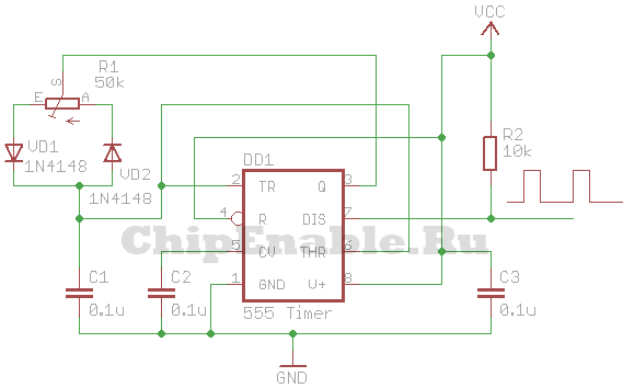
To generate a PWM signal, you can take a circuit based on the NE555 chip. The simplest DC motor speed controller circuit is shown in the figure:
Schematic diagram of the DC motor controller

Here VT1 is an n-type field effect transistor capable of withstanding the maximum motor current at a given voltage and load on the shaft. VCC1 is 5 to 16V, VCC2 is greater than or equal to VCC1. The frequency of the PWM signal can be calculated using the formula:
where R1 is in ohms, C1 is in farads.
With the ratings indicated in the diagram above, the PWM signal frequency will be equal to:
F = 1.44/(50000*0.0000001) = 290 Hz.
It is worth noting that even modern devices, including high-power control, are based on just such schemes. Naturally, using more powerful elements that can withstand high currents.
PWM - engine speed controllers on the 555 timer
 The 555 timer is widely used in control devices, for example, in PWM - speed controllers for DC motors.
Everyone who has ever used a cordless screwdriver has probably heard a squeak coming from the inside. It is the motor windings whistling under the influence of the impulse voltage generated by the PWM system.
Another way to regulate the speed of an engine connected to a battery is simply indecent, although it is quite possible. For example, simply connect a powerful rheostat in series with the motor, or use an adjustable linear voltage regulator with a large heatsink.
A variant of the PWM controller based on the 555 timer is shown in Figure 1.
The circuit is quite simple and everything is based on a multivibrator, though converted into a pulse generator with adjustable duty cycle, which depends on the ratio of the charge and discharge rate of the capacitor C1.
The capacitor is charged along the circuit: + 12V, R1, D1, the left side of the resistor P1, C1, GND. And the capacitor is discharged along the circuit: the upper plate C1, the right side of the resistor P1, the diode D2, pin 7 of the timer, the lower plate C1. By rotating the slider of the resistor P1, you can change the ratio of the resistances of its left and right parts, and therefore the time of charging and discharging the capacitor C1, and as a result, the duty cycle of the pulses.

Figure 1. Schematic of the PWM controller on the 555 timer
This scheme is so popular that it is already available in the form of a set, which is shown in the following figures.


Figure 2. Schematic diagram of a set of PWM - regulator.
Timing diagrams are also shown here, but, unfortunately, the ratings of the parts are not shown. They can be seen in Figure 1, for which, in fact, it is shown here. Instead of the TR1 bipolar transistor, without altering the circuit, you can use a powerful field effect, which will increase the load power.
By the way, another element appeared on this circuit - diode D4. Its purpose is to prevent the discharge of the timing capacitor C1 through the power supply and the load - the motor. Thus, stabilization of the PWM frequency is achieved.
By the way, with the help of such circuits, it is possible to control not only the speed of a DC motor, but also simply an active load - an incandescent lamp or some kind of heating element.

Figure 3. The printed circuit board of the PWM regulator set.
With a little work, it is quite possible to recreate this using one of the programs for drawing printed circuit boards. Although, given the scarcity of parts, one copy will be easier to assemble by hanging.

Figure 4. Appearance of a set of PWM - regulator.
True, the already assembled branded set looks quite nice.
Here, perhaps, someone will ask a question: “The load in these regulators is connected between + 12V and the collector of the output transistor. But what about, for example, in a car, because everything is already connected to the ground, body, car?
Yes, you can’t argue against the masses, here you can only recommend moving the transistor switch into the gap of the “plus”9raquo; wires. A possible variant of such a scheme is shown in Figure 5.

Figure 6 shows the MOSFET output stage separately. The drain of the transistor is connected to +12V of the battery, the gate just “hangs9raquo; in the air (which is not recommended), a load is included in the source circuit, in our case a light bulb. This figure is shown simply to explain how a MOSFET works.

In order for the MOSFET to open, it is enough to apply a positive voltage to the gate relative to the source. In this case, the light bulb will light up to full heat and will shine until the transistor is closed.
In this figure, the easiest way to close the transistor is by shorting the gate to the source. And such a manual circuit is quite suitable for checking the transistor, but in a real circuit, especially a pulse one, you will have to add a few more details, as shown in Figure 5.
As mentioned above, an additional voltage source is required to open the MOSFET transistor. In our circuit, its role is played by the capacitor C1, which is charged along the + 12V circuit, R2, VD1, C1, LA1, GND.
To open the transistor VT1, a positive voltage must be applied to its gate from a charged capacitor C2. It is quite obvious that this will only happen when the transistor VT2 is open. And this is possible only if the optocoupler transistor OP1 is closed. Then the positive voltage from the positive plate of the capacitor C2 through the resistors R4 and R1 will open the transistor VT2.
At this point, the PWM input should be low and shunt the optocoupler LED (this is often referred to as inverting the LEDs), so the optocoupler LED is off and the transistor is off.
To close the output transistor, you need to connect its gate to the source. In our circuit, this will happen when the transistor VT3 opens, and this requires that the output transistor of the optocoupler OP1 be open.
The PWM signal at this time has a high level, so the LED is not shunted and emits the infrared rays assigned to it, the transistor of the optocoupler OP1 is open, which results in the load being turned off - the light bulb.
As one of the options for applying a similar scheme in a car, these are daytime running lights. In this case, motorists claim to use high-beam lamps that are turned on half-heartedly. Most often, these designs are on a microcontroller. there are a lot of them on the Internet, but it's easier to do it on the NE555 timer.
j&;electrician Ino - electrical engineering and electronics, home automation, l&;articles of construction and repair of home electrical wiring, sockets and switches, wires and cables, and l&;power sources l&;veta, interesting acts and much more for electricians and their home workers.
Information and teaching materials for new electricians.
Keys, examples and technical solutions, examples of interesting electrical innovations.
The information on l&;site j&;lectric Ino is provided in ok&;communal and instructive fields. For the use of this information, there is no administration of the l&;ayte of responsibility. Sai can win materials 12+
Reproduction of l&;ayte k&; materials is prohibited.
A Pulse Width Modulation based regulator circuit, or simply, can be used to change the speed of a DC motor by 12 volts. Shaft speed control using PWM gives greater performance than using a simple change in the DC voltage supplied to the motor.
PWM motor speed controller
The motor is connected to a field effect transistor VT1, which is controlled by a PWM multivibrator built on the popular NE555 timer. Due to the application, the speed control scheme turned out to be quite simple.
As already mentioned above, PWM motor speed controller performed using a simple pulse generator generated by an unstable multivibrator with a frequency of 50 Hz, performed on a NE555 timer. The signals from the output of the multivibrator provide bias at the gate of the MOSFET transistor.
The duration of the positive pulse can be adjusted with a variable resistor R2. The larger the positive pulse width of the MOSFET gate, the more power is delivered to the DC motor. And vice versa, the narrower its width, the less power is transmitted and, as a result, the engine speed. This circuit can be operated from a 12 volt power supply.
Characteristics of the transistor VT1 (BUZ11):
- Transistor type: MOSFET
- Polarity: N
- Maximum power dissipation (W): 75
- Maximum allowable drain-source voltage (V): 50
- Maximum allowable gate-source voltage (V): 20
- Maximum allowable DC drain current (A): 30
The simplest method for controlling the speed of a DC motor is based on the use of pulse width modulation (PWM or PWM). The essence of this method is that the supply voltage is applied to the motor in the form of pulses. In this case, the pulse repetition rate remains constant, while their duration may vary.
The PWM signal is characterized by such a parameter as duty cycle or Duty cycle. This value is the reciprocal of the duty cycle and is equal to the ratio of the pulse duration to its period.
D = (t/T) * 100%
The figures below show PWM signals with different duty cycles.
With this control method, the motor speed will be proportional to the duty cycle of the PWM signal.
A simple DC motor control circuit
The simplest DC motor control circuit consists of a field-effect transistor, on the gate of which a PWM signal is applied. The transistor in this circuit acts as an electronic key that switches one of the motor outputs to ground. The transistor turns on at the time of the pulse duration.

How will the engine behave in such an inclusion? If the frequency of the PWM signal is low (units of Hz), then the motor will turn jerkily. This will be especially noticeable with a small duty cycle of the PWM signal.
Circuit for generating a PWM signal
There are many circuits for generating a PWM signal. One of the simplest is a circuit based on the 555th timer. It requires a minimum of components, does not need to be configured and is assembled in one hour.
The supply voltage of the VCC circuit can be in the range of 5 - 16 Volts. As diodes VD1 - VD3, you can take almost any diodes.
If you are interested in understanding how this circuit works, you need to refer to the block diagram of the 555th timer. The timer consists of a voltage divider, two comparators, a flip-flop, an open collector switch, and an output buffer.

The power supply (VCC) and reset (Reset) outputs are connected to the positive supply, for example, +5 V, and the ground (GND) to the negative. The open collector of the transistor (output DISCH) is pulled up to the power plus through a resistor and a PWM signal is removed from it. The CONT pin is not used, a capacitor is connected to it. The outputs of the THRES and TRIG comparators are combined and connected to an RC circuit consisting of a variable resistor, two diodes and a capacitor. The middle pin of the variable resistor is connected to the OUT pin. The extreme terminals of the resistor are connected through diodes to the capacitor, which is connected to the ground by the second terminal. Due to this inclusion of diodes, the capacitor is charged through one part of the variable resistor, and discharged through the other.
At the moment the power is turned on, the OUT pin is at a low logic level, then the THRES and TRIG pins, thanks to the VD2 diode, will also be at a low level. The upper comparator will switch the output to zero, and the lower one to one. The trigger output will be set to zero (because it has an inverter at its output), the transistor switch will close, and a high level will be set at the OUT pin (because it has an inverter at its input). Next, the capacitor C3 will begin to charge through the diode VD1. When it is charged to a certain level, the lower comparator will switch to zero, and then the upper comparator will switch the output to one. The trigger output will be set to one, the transistor switch will turn on, and the OUT pin will go low. Capacitor C3 will start to discharge through the diode VD2 until it is completely discharged and the comparators switch the trigger to another state. The cycle will then repeat.
The approximate frequency of the PWM signal generated by this circuit can be calculated using the following formula:
F = 1.44/(R1*C1), [Hz]
where R1 is in ohms, C1 is in farads.
With the ratings indicated in the diagram above, the PWM signal frequency will be equal to:
F = 1.44/(50000*0.0000001) = 288 Hz.
PWM DC motor speed controller
Let's combine the two diagrams above and we get a simple circuit DC motor speed controller, which can be used to control the speed of the engine of a toy, robot, microdrill, etc.
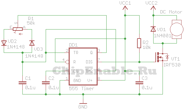
VT1 is an n-type field effect transistor capable of withstanding the maximum motor current at a given voltage and shaft load. VCC1 is 5 to 16V, VCC2 is greater than or equal to VCC1.
Instead of a field effect transistor, you can use a bipolar n-p-n transistor, a Darlington transistor, an opto-relay of the appropriate power.